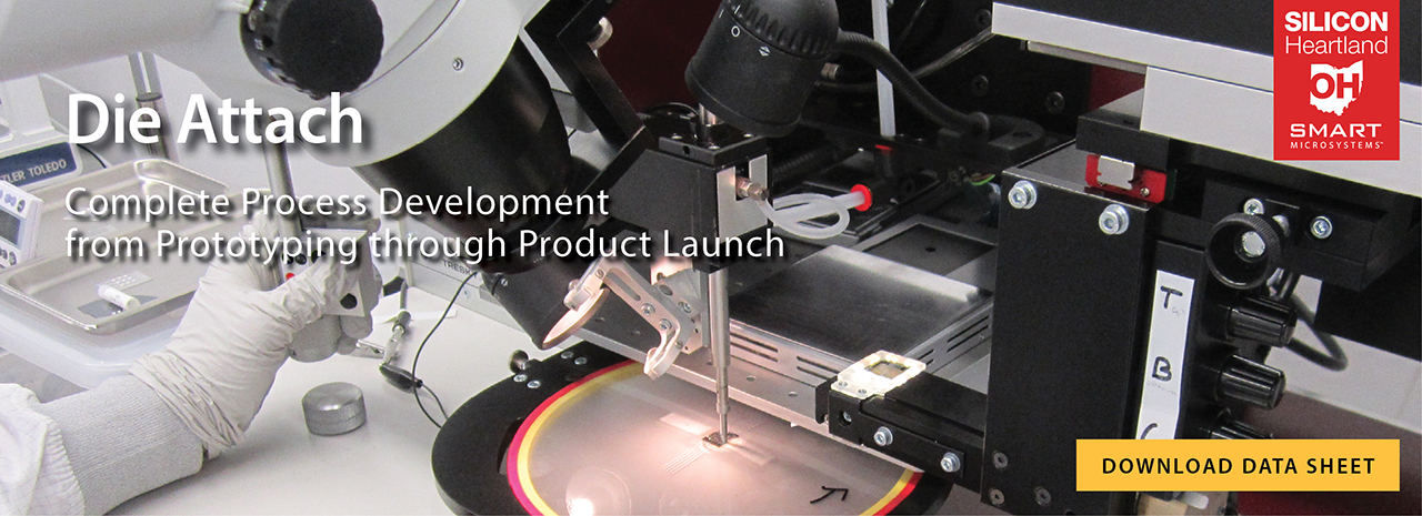

Die attach is a critical step in the packaging of microsystems and MEMS sensors that can impact other packaging and assembly processes. For example, accuracy and repeatability requirements for die placement and die height can affect other package assembly processes such as wire bonding as well as the adhesive and encapsulation materials used. The die attach capabilities and expertise at SMART Microsystems support the process development, testing, and manufacturing of sub-assemblies designed by our customers allowing them to quickly realize a microelectronic package assembly solution for their products. For additional information you can call or send us an email to discuss your die attach needs.
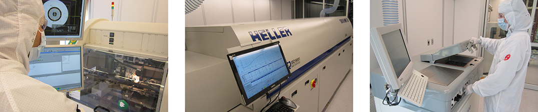
VACUUM SOLDER REFLOW SPECIFICATIONS
• Flux-less and void-free soldering
• Hermetic package sealing
• Controlled cooling in N2 gas
• Automatic control of vacuum and gas backfill pressure
• Vacuum minimum 50mTorr
• Chamber gas pressure maximum 40psig
• Operating temperature range of 100 to 500°C
• Uniform heat distribution supplied by single sheet graphite heating element
• Automatic control of heating and cooling ramp rates
• Formic acid capable
• 12.0x12.0 inch thermal working area